Devfreq Developer Guide
ID: RK-KF-YF-014
Release Version: V1.0.0
Release Date: 2019-12-30
Security Level: Non-confidential
DISCLAIMER
THIS DOCUMENT IS PROVIDED “AS IS”. FUZHOU ROCKCHIP ELECTRONICS CO., LTD.(“ROCKCHIP”)DOES NOT PROVIDE ANY WARRANTY OF ANY KIND, EXPRESSED, IMPLIED OR OTHERWISE, WITH RESPECT TO THE ACCURACY, RELIABILITY, COMPLETENESS,MERCHANTABILITY, FITNESS FOR ANY PARTICULAR PURPOSE OR NON-INFRINGEMENT OF ANY REPRESENTATION, INFORMATION AND CONTENT IN THIS DOCUMENT. THIS DOCUMENT IS FOR REFERENCE ONLY. THIS DOCUMENT MAY BE UPDATED OR changeED WITHOUT ANY NOTICE AT ANY TIME DUE TO THE UPGRADES OF THE PRODUCT OR ANY OTHER REASONS.
Trademark Statement
“Rockchip”, “瑞芯微”, “瑞芯” shall be Rockchip’s registered trademarks and owned by Rockchip. All the other trademarks or registered trademarks mentioned in this document shall be owned by their respective owners.
All rights reserved. ©2019. Fuzhou Rockchip Electronics Co., Ltd.
Beyond the scope of fair use, neither any entity nor individual shall extract, copy, or distribute this document in any form in whole or in part without the written approval of Rockchip.
Fuzhou Rockchip Electronics Co., Ltd.
No.18 Building, A District, No.89, software Boulevard Fuzhou, Fujian,PRC
Website: www.rock-chips.com
Customer service Tel: +86-4007-700-590
Customer service Fax: +86-591-83951833
Customer service e-Mail: fae@rock-chips.com
Preface
Overview
This document mainly describes the related concepts, configuration methods and user interface of Devfreq.
Product Version
| Chipset | Kernel Version |
|---|---|
| All | Linux4.4, Linux4.19 |
Intended Audience
This document (this guide) is mainly intended for:
Technical support engineers Software development engineers
Revision History
| Version | Author | Date | Change Description |
|---|---|---|---|
| V1.0.0 | Finley Xiao | 2019-12-30 | Initial version |
Content
[TOC]
Introduction
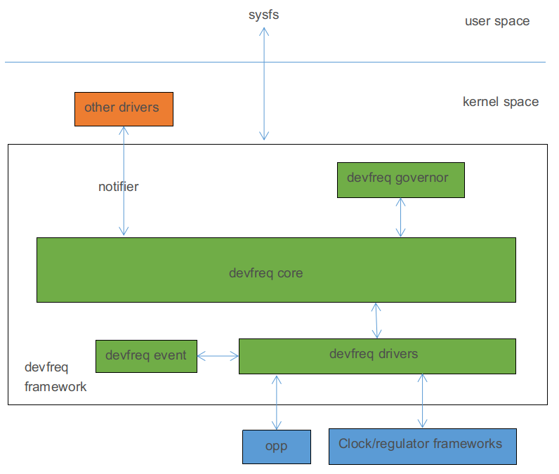
Devfreq is a framework model defined by kernel developer to dynamically change frequency and voltage according to specified governor. It can be effective to lower power consumption with taking into account the performance. Devfreq is similar to CPUFreq, but CPUFreq is only used for CPU, and Devfreq is used for modules that require changing frequency dynamically in addition to the CPU. The Devfreq framework consists of governor, core, driver and event. The software framework is as follows:
Devfreq governor:It is used to determine when to change the frequency and which frequency will be change to. The kernel includes the following governor:
-
simple ondemand:Change frequency dynamically according to load.
-
userspace:A user interface provided for user mode application to change frequency.
-
powersave:Prefer power consumption and set frequency to the lowest value always.
-
performance:Prefer performance and set frequency to the highest value always.
-
dmc ondemand:Based on simple ondemand and support changing frequency according to scenes and vop bandwidth, it is dedicated to DDR frequency scaling.
Devfreq core: Encapsulate and abstract the devfreq governors, devfreq drivers and define a clear interface.
Devfreq driver:Use to initialize frequency table and set target frequency.
Devfreq event:It is used to monitor load information of device.
Code Path
Governor related code:
drivers/devfreq/governor_simpleondemand.c        /* simple ondemand governor */
drivers/devfreq/governor_performance.c           /* performance governor */
drivers/devfreq/governor_powersave.c             /* powersave governor */
drivers/devfreq/governor_userspace.c             /* userspace governor */
drivers/devfreq/rockchip_dmc.c                   /* dmc ondemand governor */
Event related code:
drivers/devfreq/devfreq-event.c
drivers/devfreq/event/rockchip-dfi.c  /* monitor DDR read and write cycles */
drivers/devfreq/event/rockchip-nocp.c /* monitor bytes accessed by each module */
Core related code:
drivers/devfreq/devfreq.c
Driver related code:
drivers/devfreq/rockchip_dmc.c                                     /* DMC driver */
drivers/gpu/arm/midgard/backend/gpu/mali_kbase_devfreq.c           /* GPU driver */
drivers/gpu/arm/bifrost_for_linux/backend/gpu/mali_kbase_devfreq.c /* GPU driver */
drivers/gpu/arm/bifrost/backend/gpu/mali_kbase_devfreq.c           /* GPU driver */
drivers/gpu/arm/mali400/mali/linux/mali_devfreq.c                  /* GPU driver */
drivers/devfreq/rockchip_bus.c                                     /* bus driver */
drivers/soc/rockchip/rockchip_opp_select.c                      /* interface for opp */
Menuconfig Configuration
Device Drivers  --->
	[*] Generic Dynamic Voltage and Frequency Scaling (DVFS) support  --->
		--- Generic Dynamic Voltage and Frequency Scaling (DVFS) support
			*** DEVFREQ Governors ***           /* devfreq governor */
		-*-   Simple Ondemand
		<*>   Performance
		<*>   Powersave
			*** DEVFREQ Drivers ***
		<*>   ARM ROCKCHIP BUS DEVFREQ Driver   /* bus devfreq driver */
		<*>   ARM ROCKCHIP DMC DEVFREQ Driver   /* dmc devfreq driver */
		[*]   DEVFREQ-Event device Support  --->
			--- DEVFREQ-Event device Support
			-*-   ROCKCHIP DFI DEVFREQ event Driver  /* dfi event driver */
			/* nocp event driver */
			<*>   ROCKCHIP NoC (Network On Chip) Probe DEVFREQ event Driver
Please modify the configuration for different platforms according to the actual situation.
Device Tree Configuration
GPU DVFS Configuration
Clock Configuration
According to the actual situation of the platform, add "clock" and "clock-names" properties to GPU node, which is generally in the DTSI file. If you need more detail about configuration description of clock, please refer to the related Rockchip clock development documentation. Take RK3399 as an example:
gpu: gpu@ff9a0000 {
	compatible = "arm,malit860",
				 "arm,malit86x",
				 "arm,malit8xx",
				 "arm,mali-midgard";
	...
	clocks = <&cru ACLK_GPU>;
	clock-names = "clk_mali";
	...
};
Regulator Configuration
According to the power solution of product hardware, add “mali-supply” property to the GPU node, which is generally board-level DTS file. For detailed configuration instructions for Regulator, please refer to the development documentation related to Regulator and PMIC. Take RK3399 as an example:
&i2c0 {
	...
	vdd_gpu: syr828@41 {
		compatible = "silergy,syr828";
		reg = <0x41>;
		vin-supply = <&vcc5v0_sys>;
		regulator-compatible = "fan53555-reg";
		pinctrl-0 = <&vsel2_gpio>;
		vsel-gpios = <&gpio1 14 GPIO_ACTIVE_HIGH>;
		regulator-name = "vdd_gpu";
		regulator-min-microvolt = <712500>;
		regulator-max-microvolt = <1500000>;
		regulator-ramp-delay = <1000>;
		fcs,suspend-voltage-selector = <1>;
		regulator-always-on;
		regulator-boot-on;
		regulator-initial-state = <3>;
			regulator-state-mem {
			regulator-off-in-suspend;
		};
	};
};

&gpu {
	status = "okay";
	mali-supply = <&vdd_gpu>;
};
OPP Table Configuration
The kernel puts the related configuration of frequency and voltage in the devicetree. These nodes make up by configuration information is called OPP Table. The OPP Table node contains the frequency and voltage of OPP nodes, leakage configuration properties, and PVTM configuration properties.
For detailed configuration instructions of OPP, refer to the following documents:
Documentation/devicetree/bindings/opp/opp.txt
Documentation/power/opp.txt
Add OPP Table
According to the actual situation of the platform, add an OPP Table node and add "operating-points-v2" property to the GPU node, generally in the DTSI file. Take RK3399 as an example:
&gpu {
	operating-points-v2 = <&gpu_opp_table>;
};

gpu_opp_table: opp-table2 {
	compatible = "operating-points-v2";

	opp-200000000 {
		opp-hz = /bits/ 64 <200000000>;         /* unit in Hz */
		opp-microvolt = <800000>;               /* unit in uV */
	};
	...
	opp-800000000 {
		opp-hz = /bits/ 64 <800000000>;
		opp-microvolt = <1100000>;
	};
}
Delete OPP
If the developer needs to delete some frequency points, the following method can be used.
Method 1: Add "status = "disabeld";" to the corresponding OPP node, for example:
gpu_opp_table: opp-table2 {
	compatible = "operating-points-v2";

	opp-200000000 {
		opp-hz = /bits/ 64 <200000000>;         /* unit in Hz */
		opp-microvolt = <800000>;               /* unit in uV */
	};
	...
	opp-800000000 {
		opp-hz = /bits/ 64 <800000000>;
		opp-microvolt = <1100000>;
		status = "disabled";
	};
}
Method 2: Re-quote the OPP Table node in the board-level DTS and add "status = "disabeld";" to the corresponding OPP node, for example:
&gpu_opp_table {
	opp-800000000 {
		status = "disabled";
	};
};
Modify OPP Table According to Leakage
IDDQ (Integrated Circuit Quiescent Current) , we also call it leakage. The GPU's leakage means the quiescent current of GPU when provide a specific voltage. If the GPU is in VD logic, the GPU's leakage is equivalent to the logic leakage, which means providing a specific voltage to the VD logic, and get the quiescent current value. At chip producing, the leakage value will be written to eFuse or OTP.
Modify Voltage According to Leakage
Background: we find that the Vmin of small leakage chips is larger than big leakage chips from test, so we can reduce the voltage for big leakage chips to reduce power consumption and improve performance.
Function description: get the GPU leakage value from eFuse or OTP and get the voltage selector corresponding to the leakage from a particular table, then we can find a property "opp-microvolt-<selector>" in each OPP, it is the target voltage for the OPP.
Configuration method: Firstly, you need to add related code for eFuse or OTP. For details, please refer to the related documents of eFuse and OTP. Then add three properties "rockchip, leak-voltage-sel", "nvmem-cells", and "nvmem-cell-names" to the OPP Table node. At the same time, add "opp-microvolt-<name>" to the OPP node according to the actual conditions. These configurations are generally in the DTSI file. Take RK3328 as an example:
gpu_opp_table: gpu-opp-table {
	compatible = "operating-points-v2";

	/*
	 * Get GPU leakage from eFuse or OTP
	 */
	nvmem-cells = <&gpu_leakage>;
	nvmem-cell-names = "gpu_leakage";

	/*
	 * If leakage is between 1mA and 10mA, OPP will use the voltage specified by
	 * opp-microvolt-L0.
	 * If leakage is between 11mA and 254mA, OPP will use the voltage specified by
	 * opp-microvolt-L1
	 *
	 * If delete "rockchip,leakage-voltage-sel" or leakage exceed the range, OPP will
	 * use the voltage specified by "opp-microvolt".
	 */
	rockchip,leakage-voltage-sel = <
		1   10    0
		11  254   1
	>;

	opp-200000000 {
		opp-hz = /bits/ 64 <200000000>;
		opp-microvolt = <950000>;
		opp-microvolt-L0 = <950000>;
		opp-microvolt-L1 = <950000>;
	};
	...
	opp-500000000 {
		opp-hz = /bits/ 64 <500000000>;
		opp-microvolt = <1150000>;
		opp-microvolt-L0 = <1150000>;
		opp-microvolt-L1 = <1100000>;
	};
};
To turn off this feature, you can delete the property"rockchip, leak-voltage-sel" , then OPP will use the voltage specified by "opp-microvolt".
Modify OPP Table According to PVTM
GPU PVTM (Process-Voltage-Temperature Monitor) is a module located near GPU, which can reflect the difference in performance between chips. It is affected by process, voltage and temperature.
Modify Voltage According to PVTM
Background: we find that the Vmin of small PVTM chips is larger than big PVTM chips from test, so we can reduce the voltage for big PVTM chips to reduce power consumption and improve performance.
Function description: get the PVTM value at the specified voltage and frequency and convert it to the PVTM value at the reference temperature, and get the voltage selector corresponding to the PVTM from a particular table, then we can find a property "opp-microvolt-<selector>" in each OPP, it is the target voltage for the OPP.
Configure method: Firstly, add the related code for PVTM. For code details, please refer to the related documents of PVTM. Then add properties "rockchip, pvtm-voltage-sel", "rockchip, thermal-zone" and "rockchip, pvtm-<name>" to the OPP Table node, in the case of various processes, add property "nvmem-cells" and "nvmem-cell-names", and add property "opp-microvolt-<name>" to OPP node according to the actual conditions. These configurations are generally in the DTSI file. Take RK3399 as an example:
gpu_opp_table: opp-table2 {
	compatible = "operating-points-v2";

	/*
	 * If PVTM value is between 0 and 121000, OPP will use the voltage specified by
	 * "opp-microvolt-L0"
	 * If PVTM value is between 121001 and 125500, OPP will use the voltage specified by
	 * "opp-microvolt-L1"
	 * If PVTM value is between 125501 and 128500, OPP will use the voltage specified by
	 * "opp-microvolt-L2"
	 * If PVTM value is between 128501 and 999999, OPP will use the voltage specified by
	 * "opp-microvolt-L3"
	 *
	 * If deleted "rockchip,pvtm-voltage-sel" or PVTM value exceeds the range of the
	 * table, OPP will use the voltage specified by "opp-microvolt".
	 */
	rockchip,pvtm-voltage-sel = <
		0        121000   0
		121001   125500   1
		125501   128500   2
		128501   999999   3
	>;
	/* Before get PVTM value, change GPU frequency to 200000Khz */
	rockchip,pvtm-freq = <200000>;
	/* Before get PVTM value, change GPU voltage to 900000uV */
	rockchip,pvtm-volt = <900000>;
	/* PVTM channel, format <channel sel> */
	rockchip,pvtm-ch = <3 0>;
	rockchip,pvtm-sample-time = <1000>;     /* PVTM sampling time, unit is us */
	rockchip,pvtm-number = <10>;            /* PVTM sampling number */
	rockchip,pvtm-error = <1000>;       /* error can be afford between sampling data */
	rockchip,pvtm-ref-temp = <41>;          /* refrence temperature */
	/*
	 * Proportional coefficient of temperature, when below reference temperature use the
	 * first coefficient, when higher use the second one
	 */
	rockchip,pvtm-temp-prop = <46 12>;
	rockchip,thermal-zone = "gpu-thermal";  /* get temperature from soc-thermal */

	opp-200000000 {
		opp-hz = /bits/ 64 <200000000>;
		opp-microvolt = <800000>;
		opp-microvolt-L0 = <800000>;
		opp-microvolt-L1 = <800000>;
		opp-microvolt-L2 = <800000>;
		opp-microvolt-L3 = <800000>;
	};
	...
	opp-800000000 {
		opp-hz = /bits/ 64 <800000000>;
		opp-microvolt = <1100000>;
		opp-microvolt-L0 = <1100000>;
		opp-microvolt-L1 = <1075000>;
		opp-microvolt-L2 = <1050000>;
		opp-microvolt-L3 = <1025000>;
	};
};
To turn off this feature, you can delete the property "rockchip, pvtm-voltage-sel" , OPP will use the voltage specified by "opp-microvolt".
Modify OPP Table According to IR-Drop
IR-Drop is a phenomenon that a voltage drop or rise in power and ground networks in integrated circuits. Here we consider it as the ripple voltage case by power ripple and board layout.
Background: It has been found that some customer's solution have poor ripple voltage. If use the same OPP Table as EVB, the voltage of some frequency will be low, which affects system stability. In this case, the OPP Table needs to be adjusted according to IR-Drop.
Function description: The difference between the ripple of the EVB and he ripple of prototype board at each frequency is the volage that needs to add for this frequency.
Configuration method: Add properies "rockchip, max-volt", "rockchip, evb-irdrop" and "rockchip, board-irdrop" to the OPP Table node , "rockchip, board-irdrop" is generally configured in the board-level DTS file, others are configured in the DTSI file.
Taking RK3326 as an example, the DTSI is configured as follows:
gpu_opp_table: gpu-opp-table {
	compatible = "operating-points-v2";

	rockchip,max-volt = <1175000>; /* the highest voltage, unit is uV */
	rockchip,evb-irdrop = <25000>; /* ripple voltage of EVB or SDK */
	...
}
The board-level DTS is configured as follows:
&gpu_opp_table {
	/*
	 * max IR-drop values on different freq condition for this board!
	 */
	/*
	 * ripple voltage at diffrent frequencies
	 * If frequency is between 200Mhz-520MHz, ripple voltage is 50000uV, the target
	 * voltage will add 25000uV(50000-25000(EVB ripple voltage))
	 */
	rockchip,board-irdrop = <
		/* MHz	MHz	uV */
		   200	520 50000
	>;
};
To turn off this feature, delete property “rockchip,board-irdrop”.
Wide Temperature Configuration
Wide temperature usually means ambient temperature is from − 40℃ to + 85℃.
Background: It has been found that some platforms are unstable in low temperature environment and can be stable after raised voltage at some frequency. In this case, the voltage needs to be adjust according to the temperature.
Function description: When the system detects that the temperature is lower than a specific value, it will raises the voltage of each frequency. If the voltage of some frequency exceeds the maximum voltage ristricted by system, these frequency will be prohibited, that is, working without these frequencies. When the temperature returns to normal temperature, the voltage returns to the default state.
Configuration method: To support low temperature, add properties "rockchip, temp-hysteresis", "rockchip, low-temp", "rockchip, low-temp-min-volt", "rockchip, low-temp-adjust-volt", "rockchip, max-volt" to the OPP Table node.
These configurations are generally in the DTSI file, take RK3399 as an example:
gpu_opp_table: opp-table2 {
	compatible = "operating-points-v2";

	/*
	 * Hysteresis parameter, unit is millicelusius, prevent from entry into low
	 * temperatures or high temperatures frequently
	 * For example, when temperature less than 0 Celsius degrees, work on the low
	 * temperature state, higher than 5 Celsius degrees, return to normal state.
	 */
	rockchip,temp-hysteresis = <5000>;
	rockchip,low-temp = <0>;        /* Threshold for low temperature, millicelsius */
	rockchip,low-temp-min-volt = <900000>; /* Minimum voltage at low temperature, uV */
	/* At lower temperature state, add 25mV to frequency at 0-800MHz */
	rockchip,low-temp-adjust-volt = <
		/* MHz    MHz    uV */
		   0      800    25000
	>;
	rockchip,max-volt = <1150000>;  /* highest voltage, unit is uV */
	...
}
Upthreshold and Downdifferential Configuration
Background: The simple ondemand governor has two parameters, upthreshold and downdifferential, the default values are 90 and 5. When the load exceeds 90%, the frequency is adjusted to the highest frequency. When the load is less than 90% and greater than 90%-5%, don't change the current frequency. When the load is less than 90%-5%, frequency will be adjusted to the appropriate value, so that the load is almost 90%-5%/2. With the default configuration, in some scenarios, the GPU will not raise the frequency timely, which will result in frame loss. Therefore, need modify the configuration.
Configuration method: Add property “upthreshold” and “downdifferential” to the GPU node.
These configurations are generally in the DTSI file, take RK3288 as an example:
gpu: gpu@ffa30000 {
	compatible = "arm,malit764",
				 "arm,malit76x",
				 "arm,malit7xx",
				 "arm,mali-midgard";
	reg = <0x0 0xffa30000 0x0 0x10000>;

	upthreshold = <75>;
	downdifferential = <10>;
	...
}
DMC DVFS Configuration
DMC(Dynamic Memory Controller)DVFS means scaling DDR voltage and frequency dynamically.
Clock Configuration
According to the actual situation of platform, add the "clock" property to the DMC node, which is generally the DTSI file. If you need more detail about configuration description of clock, please refer to the related Rockchip clock development documentation. Take RK3399 as an example:
dmc: dmc {
	compatible = "rockchip,rk3399-dmc";
	...
	clocks = <&cru SCLK_DDRCLK>;
	clock-names = "dmc_clk";
	...
};
Regulator Configuration
According to the actual product hardware power solution, add the “center-supply” property to the DMC node, which is generally in board-level DTS file. For detailed configuration instructions of Regulator, please refer to the development documentation related to Regulator and PMIC. Take RK3399 as an example:
&i2c0 {
	...
	rk808: pmic@1b {
		...
		regulators {
			vdd_center: DCDC_REG1 {
				regulator-always-on;
				regulator-boot-on;
				regulator-min-microvolt = <750000>;
				regulator-max-microvolt = <1350000>;
				regulator-ramp-delay = <6001>;
				regulator-name = "vdd_center";
				regulator-state-mem {
					regulator-off-in-suspend;
				};
			};
		};
	};
};

&dmc {
	status = "okay";
	center-supply = <&vdd_center>;
};
OPP Table Configuration
The kernel puts the related configuration of frequency and voltage in the devicetree. These nodes make up by configuration information is called OPP Table. The OPP Table node contains the frequency and voltage of OPP nodes, leakage configuration properties, and PVTM configuration properties.
For detailed configuration instructions of OPP, refer to the following documents:
Documentation/devicetree/bindings/opp/opp.txt
Documentation/power/opp.txt
Add OPP Table
According to the actual situation of the platform, add an OPP Table node and add the "operating-points-v2" property to DMC node, generally in the DTSI file. Take RK3399 as an example:
&dmc {
	operating-points-v2 = <&dmc_opp_table>;
};

dmc_opp_table: opp-table3 {
	compatible = "operating-points-v2";

	opp-200000000 {
		opp-hz = /bits/ 64 <200000000>;         /* Hz */
		opp-microvolt = <900000>;               /* uV */
	};
	...
	opp-800000000 {
		opp-hz = /bits/ 64 <800000000>;
		opp-microvolt = <900000>;
	};
};
Delete OPP
If the developer needs to delete some frequency points, the following method can be used.
Method 1: Add "status = "disabeld";" to the corresponding OPP node, for example:
dmc_opp_table: opp-table3 {
	compatible = "operating-points-v2";

	opp-200000000 {
		opp-hz = /bits/ 64 <200000000>;         /* Hz */
		opp-microvolt = <800000>;               /* uV */
	};
	...
	opp-800000000 {
		opp-hz = /bits/ 64 <800000000>;
		opp-microvolt = <900000>;
		status = "disabled";
	};
}
Method 2: Re-quote the "OPP Table" node in the board-level DTS and add "status = "disabeld";" to the corresponding OPP node, for example:
&dmc_opp_table {
	opp-800000000 {
		status = "disabled";
	};
};
Modify OPP Table According to Leakage
IDDQ (Integrated Circuit Quiescent Current) , we also call it leakage. The DDR's leakage means the quiescent current of DDR when provide a specific voltage. At chip producing, the leakage value will be written to eFuse or OTP.
Modify Voltage According to Leakage
Background: we find that the Vmin of small leakage chips is larger than big leakage chips from test, so we can reduce the voltage for big leakage chips to reduce power consumption and improve performance.
Function description: get the DDR leakage value from eFuse or OTP and get the voltage selector corresponding to the leakage from a particular table, then we can find a property "opp-microvolt-<selector>" in each OPP, it is the target voltage for the OPP.
Configure method: Firstly, you need to add related code for eFuse or OTP. For details, please refer to the related documents of eFuse and OTP. Then, add three properties "rockchip, leakage-voltage-sel", "nvmem-cells", and "nvmem-cell-names" at OPP Table node. Meanwhile, add the "opp-microvolt-<name>" property at OPP node according to the actual conditions. These configurations are generally in the "DTSI " file. Take RK3328 as an example:
dmc_opp_table: dmc-opp-table {
	compatible = "operating-points-v2";

	/*
	 * Get DDR leakage from eFuse or OTP
	 */
	nvmem-cells = <&logic_leakage>;
	nvmem-cell-names = "ddr_leakage";

	/*
	 * If leakage is between 1mA and 10mA, OPP will use the voltage specified by
	 * opp-microvolt-L0.
	 * If leakage is between 11mA and 254mA, OPP will use the voltage specified by
	 * opp-microvolt-L1
	 *
	 * If delete "rockchip,leakage-voltage-sel" or leakage exceed the range, OPP will
	 * use the voltage specified by "opp-microvolt".
	 */
	rockchip,leakage-voltage-sel = <
		1   10    0
		11  254   1
	>;

	opp-400000000 {
		opp-hz = /bits/ 64 <400000000>;
		opp-microvolt = <950000>;
		opp-microvolt-L0 = <950000>;
		opp-microvolt-L1 = <950000>;
	};
	...
	opp-1066000000 {
		opp-hz = /bits/ 64 <1066000000>;
		opp-microvolt = <1175000>;
		opp-microvolt-L0 = <1175000>;
		opp-microvolt-L1 = <1150000>;
	};
};
To turn off this feature, you can delete property "rockchip, leakage-voltage-sel" , then OPP will use the voltage specified by "opp-microvolt".
Modify OPP According to PVTM
Modify Voltage According to PVTM
Background: we find that the Vmin of small PVTM chips is larger than big PVTM chips from test, so we can reduce the voltage for big PVTM chips to reduce power consumption and improve performance.
Function description: get the PVTM value at the specified voltage and frequency and convert it to the PVTM value at the reference temperature, and get the voltage selector corresponding to the PVTM from a particular table, then we can find a property "opp-microvolt-<selector>" in each OPP, it is the target voltage for the OPP.
Configure method: Firstly, add the related code for PVTM. For code details, please refer to the related documents of PVTM. Then add properties "rockchip, pvtm-voltage-sel", "rockchip, thermal-zone" and "rockchip, pvtm-<name>" to the OPP Table node, in the case of various processes, add property "nvmem-cells" and "nvmem-cell-names", and add property "opp-microvolt-<name>" to OPP node according to the actual conditions. These configurations are generally in the DTSI file. Take PX30 as an example:
dmc_opp_table: dmc-opp-table {
	compatible = "operating-points-v2";

	/*
	 * If PVTM value is between 0 and 50000, OPP will use the voltage specified by "opp-
	 * microvolt-L0"
	 * If PVTM value is between 50001 and 54000, OPP will use the voltage specified by
	 * "opp-microvolt-L1"
	 * If PVTM value is between 54001 and 60000, OPP will use the voltage specified by
	 * "opp-microvolt-L2"
	 * If PVTM value is between 60001 and 99999, OPP will use the voltage specified by
	 * "opp-microvolt-L3"
	 *
	 * If deleted "rockchip,pvtm-voltage-sel" or PVTM value exceeds the range of the
	 * table, OPP will use the voltage specified by "opp-microvolt".
	 */
	rockchip,pvtm-voltage-sel = <
		0        50000   0
		50001    54000   1
		54001    60000   2
		60001    99999   3
	>;
	/* PVTM channel, format <channel sel>, here reuse the PVTM value of the CPU */
	rockchip,pvtm-ch = <0 0>;

	opp-194000000 {
		opp-hz = /bits/ 64 <194000000>;
		opp-microvolt = <950000>;
		opp-microvolt-L0 = <950000>;
		opp-microvolt-L1 = <950000>;
		opp-microvolt-L2 = <950000>;
		opp-microvolt-L3 = <950000>;
	};
	...
	opp-786000000 {
		opp-hz = /bits/ 64 <786000000>;
		opp-microvolt = <1100000>;
		opp-microvolt-L0 = <1100000>;
		opp-microvolt-L1 = <1050000>;
		opp-microvolt-L2 = <1025000>;
		opp-microvolt-L3 = <1000000>;
		status = "disabled";
	};
};
To turn off this feature, you can delete the property "rockchip, pvtm-voltage-sel" , OPP will use the voltage specified by "opp-microvolt".
Modify OPP Table According to IR-Drop
IR-Drop is a phenomenon that a voltage drop or rise in power and ground networks in integrated circuits. Here we consider it as the ripple voltage case by power ripple and board layout.
Background: It has been found that some customer's solution have poor ripple voltage. If use the same OPP Table as EVB, the voltage of some frequency will be low, which affects system stability. In this case, the OPP Table needs to be adjusted according to IR-Drop.
Function description: The difference between the ripple of the EVB and he ripple of prototype board at each frequency is the volage that needs to add for this frequency.
Configuration method: Add properies "rockchip, max-volt", "rockchip, evb-irdrop" and "rockchip, board-irdrop" to the OPP Table node , "rockchip, board-irdrop" is generally configured in the board-level DTS file, others are configured in the DTSI file. Taking RK3326 as an example, the DTSI is configured as follows:
dmc_opp_table: dmc-opp-table {
	compatible = "operating-points-v2";

	rockchip,max-volt = <1150000>; /* the highest voltage, unit is uV */
	rockchip,evb-irdrop = <25000>; /* ripple voltage of EVB or SDK */
	...
}
The board-level DTS is configured as follows:
&dmc_opp_table {
	/*
	 * max IR-drop values on different freq condition for this board!
	 */
	/*
	 * ripple voltage at diffrent frequencies
	 * If frequency is between 451Mhz-800MHz, ripple voltage is 75000uV, the target
	 * voltage will add 50000uV(75000-25000(EVB ripple voltage))
	 */
	rockchip,board-irdrop = <
		/* MHz	MHz	uV */
		   451	800	75000
	>;
};
To turn off this feature, delete property “rockchip,board-irdrop”.
Change Frequency According to scenario
Background: If fixed DDR frequency, the higher frequency, the higher power consumption, and the lower frequency, the poor performance, it is difficult to meet product requirements. For certain scenarios where DDR bandwith are relatively clear, such as benchmark, video, standby, etc., dynamically increasing or decreasing the DDR frequency to meet their different needs for performance or power consumption.
Function description: When the system enters certain special scenes, modify the DDR frequency to the frequency specified by the scenario. If entering multiple scenes at the same time, it will take the maximum value. It is noted that in the scenarios SYS_STATUS_DUALVIEW and SYS_STATUS_DUALVIEW, it cannot support DDR frequency scaling, so after entering these two scenarios, even if you enter the scene with higher DDR frequency, the DDR frequency will keep util exit these two scenarios.
Configuration method: Add the “system-status-freq” property to the DMC node, taking RK3399 as an example:
&dmc {
	status = "okay";
	...
	system-status-freq = <
		/* system status        freq(KHz) */
		/*
		 * Except for the scenarios defined below, this frequency is constant used in
		 * other scenarios
		 */
		SYS_STATUS_NORMAL       800000
		SYS_STATUS_REBOOT       528000  /* set frequency before reboot */
		SYS_STATUS_SUSPEND      200000  /* set frequency after screen is off */
		SYS_STATUS_VIDEO_1080P  200000  /* set frequency before play 1080p video */
		SYS_STATUS_VIDEO_4K     600000  /* set frequency before play 4k video*/
		SYS_STATUS_VIDEO_4K_10B 800000  /* set frequency before play 4k 10bit video */
		SYS_STATUS_PERFORMANCE  800000  /* set frequency before run benchmark */
		/* modified the minimum frequency after touching the screen */
		SYS_STATUS_BOOST        400000
		/* fixed DDR frequency before the second screen display*/
		SYS_STATUS_DUALVIEW     600000
		SYS_STATUS_ISP          600000  /* fix DDR frequency before ISP work */
	>;
}
Change Frequency According to Load
Background: There are few scenarios can be covered, the others need to dynamically change the DDR frequency according to the DDR utilization to optimize performance and power consumption.
Function description: it can detect the utilization of DDR regularly, select a target frequency according to the simple ondeman algorithm with considering the specific scenario requirements for DDR bandwidth , a maximum value will be ultimately selected. It should be noted that, under the scenario SYS_STATUS_DUALVIEW and SYS_STATUS_ISP, the DDR frequency is fixed.
Configuration method: add the properties "devfreq-events", "upthreshold", "downdifferential", "System-status-freq", "auto-min-freq" and "auto-freq-en" to the DMC node, taking RK3399 as an example:
&dmc {
	status = "okay";
	...
	devfreq-events = <&dfi>;            /* Monitor DDR utilization through dfi */
	/*
	 * When the load exceeds 40%, change to the highest frequency,
	 * When the load is less than 40% and greater than 40% -20%, maintain the current
	 * frequency
	 * When the load is less than 40% -20%, it will be change to a frequency so that
	 * the load is almost equals to 40% - 20% / 2.
	 */
	upthreshold = <40>;
	downdifferential = <20>;
	system-status-freq = <
		/* system status        freq(KHz) */
		/*
		 * Except for the scenarios defined below, this frequency is constant used in
		 * other scenarios
		 */
		SYS_STATUS_NORMAL       800000
		SYS_STATUS_REBOOT       528000  /* set frequency before reboot */
		SYS_STATUS_SUSPEND      200000  /* set frequency after screen is off */
		SYS_STATUS_VIDEO_1080P  200000  /* set frequency before play 1080p video */
		SYS_STATUS_VIDEO_4K     600000  /* set frequency before play 4k video*/
		SYS_STATUS_VIDEO_4K_10B 800000  /* set frequency before play 4k 10bit video */
		SYS_STATUS_PERFORMANCE  800000  /* set frequency before run benchmark */
		/* modified the minimum frequency after touching the screen */
		SYS_STATUS_BOOST        400000
		/* fixed DDR frequency before the second screen display*/
		SYS_STATUS_DUALVIEW     600000
		SYS_STATUS_ISP          600000  /* fix DDR frequency before ISP work */
	>;
	/*
	 * In addition to the scenarios defined above, set the minimum frequency for other
	 * scenarios to prevent the screen splash.
	 */
	auto-min-freq = <400000>;
	auto-freq-en = <1>;                 /* 1 is enabled, 0 is disabled */
};
Change Frequency According to VOP Bandwidth
Background: After enable the auto-freq , the property "auto-min-freq" needs to be added to limit the minimum frequency to prevent splash screen. So there is still space for power optimization in these scenarios, we can modify the DDR frequency based on the VOP bandwidth.
Function description: Before each frame displayed, the VOP driver firstly calculates the DDR bandwidth requirement of this frame, and then modifies the minimum frequency of DDR according to the bandwidth.
Configuration method: Add the property "vop-bw-dmc-freq" to the DMC node, taking RK3399 as an example:
&dmc {
	status = "okay";
	...
	/*
	 * bandwidth is 0-577MB/s, the minimum DDR frequency is 200MHz.
	 * bandwidth is 578-1701MB/s, the minimum DDR frequency is 300MHz.
	 * bandwidth is 1702-99999MB/s, the minimum DDR frequency is 400MHz.
	 */
	vop-bw-dmc-freq = <
	/* min_bw(MB/s) max_bw(MB/s) freq(KHz) */
		0       577      200000
		578     1701     300000
		1702    99999    400000
	>;
	/*
	* After support changing frequency according to VOP bandwidth, this value can be
	* changed to a low frequency.
	*/
	auto-min-freq = <200000>;
};
BUS DVFS Configuration
In addition to GPU and DMC, there are some modules that also need to change frequency and voltage dynamically, such as PLL, CCI, etc., we will classify them into BUS DVFS.
PLL DVFS Configuration
Background: It is found that when the frequency of the PLL exceed a certain value on some platforms, the voltage domain in which the PLL is located needs to raise voltage, so the voltage needs to be modified according to the frequency of the PLL.
Function description: Monitor the PLL frequency by registering the clock notifier. If the PLL frequency is raising, first raise the voltage and then increase the frequency. If the PLL frequency is going down, first decrease the frequency and then decrease the voltage.
Configuration method: add property "rockchip, busfreq-policy", "clocks", "clock-names", "operating-points-v2" and"Bus-supply" to device node.
Take PX30 as an example, the DTSI file configuration is as follows
bus_apll: bus-apll {
	compatible = "rockchip,px30-bus";
	/*
	 * Use clkfreq policy to monitor PLL frequency. If PLL frequency is raising,
	 * first raise the voltage and then increase the frequency. If PLL frequency is
	 * going down, first decrease the frequency and then decrease the voltage.
	 */
	rockchip,busfreq-policy = "clkfreq";
	clocks = <&cru PLL_APLL>;                    /* Clock configuration */
	clock-names = "bus";
	operating-points-v2 = <&bus_apll_opp_table>; /* OPP Table configuration */
	status = "disabled";
};

bus_apll_opp_table: bus-apll-opp-table {
	compatible = "operating-points-v2";
	opp-shared;
	/*
	* If PLL frequency less than or equal to 1008MHz, voltage is 950mV,
	* if greater than 1008MHz, voltage is 1000mV
	*/
	opp-1512000000 {
		opp-hz = /bits/ 64 <1512000000>;
		opp-microvolt = <1000000>;
	opp-1008000000 {
		opp-hz = /bits/ 64 <1008000000>;
		opp-microvolt = <950000>;
	};
};
The board configuration is as follows:
&i2c0 {
	status = "okay";
	rk809: pmic@20 {
		compatible = "rockchip,rk809";
		reg = <0x20>;
		...
		regulators {
			vdd_logic: DCDC_REG1 {
				regulator-always-on;
				regulator-boot-on;
				regulator-min-microvolt = <950000>;
				regulator-max-microvolt = <1350000>;
				regulator-ramp-delay = <6001>;
				regulator-initial-mode = <0x2>;
				regulator-name = "vdd_logic";
				regulator-state-mem {
					regulator-on-in-suspend;
					regulator-suspend-microvolt = <950000>;
				};
			};
		}
	}
}

&bus_apll {
	/*
	 * regulator configuration,
	 * it should be modified according to the actual product hardware power solution
	 */
	bus-supply = <&vdd_logic>;
	status = "okay";
};
User Interface Introduction
After the device successfully registers devfreq, it will generate a subdirectory containing the user mode interface in the directory"/sys/class/devfreq/" , such as "ff9a0000.gpu", you can switch the governor through the user mode interface, check the current frequency, modify the frequency, etc., as follows:
available_frequencies        /* available frequencies */
available_governors          /* available devfreq governors */
cur_freq                     /* the current frequency */
governor                     /* current devfreq governor */
load                         /* current load */
max_freq                     /* the maximum frequency */
min_freq                     /* the minimum frequency */
polling_interval             /* the polling interval in ms. 0 disables polling */
target_freq                  /* the last frequency set by software*/
trans_stat                   /* scaling times and running time at each frequency */
FAQ
How to Check OPP Table
Input command below:
cat /sys/kernel/debug/opp/opp_summary
Take PX30 as an example:
 device                rate(Hz)    target(uV)    min(uV)    max(uV)
-------------------------------------------------------------------
 platform-dmc
                      194000000       950000      950000      950000
                      328000000       950000      950000      950000
                      450000000       950000      950000      950000
                      528000000       975000      975000      975000
                      666000000      1000000     1000000     1000000
 platform-ff400000.gpu
                      200000000       950000      950000      950000
                      300000000       950000      950000      950000
                      400000000      1025000     1025000     1025000
                      480000000      1100000     1100000     1100000
 platform-bus-apll
                     1008000000       950000      950000      950000
                     1512000000      1000000     1000000     1000000
How to Fix Frequency
Method 1: Disable OPPs you don't need at OPP table, leave what you need alone. Take PX30 as an example, fix GPU frequency to 400MHz.
gpu_opp_table: gpu-opp-table {
	compatible = "operating-points-v2";
	...
	opp-200000000 {
		opp-hz = /bits/ 64 <200000000>;
		opp-microvolt = <950000>;
		opp-microvolt-L0 = <950000>;
		opp-microvolt-L1 = <950000>;
		opp-microvolt-L2 = <950000>;
		opp-microvolt-L3 = <950000>;
		status = "disabled";
	};
	opp-300000000 {
		opp-hz = /bits/ 64 <300000000>;
		opp-microvolt = <975000>;
		opp-microvolt-L0 = <975000>;
		opp-microvolt-L1 = <950000>;
		opp-microvolt-L2 = <950000>;
		opp-microvolt-L3 = <950000>;
		status = "disabled";
	};
	opp-400000000 {
		opp-hz = /bits/ 64 <400000000>;
		opp-microvolt = <1050000>;
		opp-microvolt-L0 = <1050000>;
		opp-microvolt-L1 = <1025000>;
		opp-microvolt-L2 = <975000>;
		opp-microvolt-L3 = <950000>;
	};
	opp-480000000 {
		opp-hz = /bits/ 64 <480000000>;
		opp-microvolt = <1125000>;
		opp-microvolt-L0 = <1125000>;
		opp-microvolt-L1 = <1100000>;
		opp-microvolt-L2 = <1050000>;
		opp-microvolt-L3 = <1000000>;
		status = "disabled";
	};
};
Method 2: Through command at device running time. Take PX30 as an example, command as below::
/* set governor to userspace */
echo userspace > /sys/class/devfreq/ff400000.gpu/governor
/* set frequency to 400MHz */
echo 400000000 > /sys/class/devfreq/ff400000.gpu/userspace/set_freq
/* check the current frequency */
cat /sys/class/devfreq/ff400000.gpu/cur_freq
How to Check the Current Frequency
The user interface of devfreq and debugfs interface of clock allow to check frequency.
Take PX30 as an example, command as below:
/* Method 1: devfreq userspace interface */
cat /sys/class/devfreq/ff400000.gpu/cur_freq

/* Method 2: clock debug interface */
cat /sys/kernel/debug/clk/aclk_gpu/clk_rate
How to Check the Current Voltage
You can check the voltage through the debug interface of the regulator. Take PX30 as an example, check the voltage of GPU, the command is as follows:
/* here vdd_logic is not fixed name, please modify */
cat /sys/kernel/debug/regulator/vdd_logic/voltage
How to Set Voltage and Frequency Separately
Take the PX30 GPU as an example, set the frequency to 400MHz and the voltage to 1000mV.
/* set governor to userspace */
echo userspace > /sys/class/devfreq/ff400000.gpu/governor

/* set frequency to 400MHz */
echo 400000000 > /sys/kernel/debug/clk/aclk_gpu/clk_rate
cat /sys/kernel/debug/clk/aclk_gpu/clk_rate

/* set voltage to 1000mV */
echo 1000000 > /sys/kernel/debug/regulator/vdd_logic/voltage
cat /sys/kernel/debug/regulator/vdd_logic/voltage
Note: When raising the frequency, first raise voltage and then increase frequency, when frequency is going down, first reduce the frequency and then getting down the voltage.
How to Check the Voltage of the OPP
If support modifying voltage according to PVTM, input command below:
dmesg | grep pvtm
Take RK3399 as example, it will prints as below:
[    0.669456] cpu cpu0: temp=22222, pvtm=138792 (140977 + -2185)
[    0.670601] cpu cpu0: pvtm-volt-sel=0
[    0.683008] cpu cpu4: temp=22222, pvtm=148761 (150110 + -1349)
[    0.683109] cpu cpu4: pvtm-volt-sel=0
[    1.495247] rockchip-dmc dmc: Failed to get pvtm
[    3.366028] mali ff9a0000.gpu: temp=22777, pvtm=120824 (121698 + -874)
/* pvtm-volt-sel = 0, opp-microvolt-L0 property will be used in GPU OPP table */
[    3.366915] mali ff9a0000.gpu: pvtm-volt-sel=0
Similarly, if support modifying voltage according to leakage, input the following command and there will have similar print output.
dmesg | grep leakage
How to Check Current Leakage
Input command below
dmesg | grep leakage
Take RK3399 CPU as example, it will print as below:
[    0.656175] cpu cpu0: leakage=10
[    0.671092] cpu cpu4: leakage=20
[    1.492769] rockchip-dmc dmc: Failed to get leakage
/* leakage=15,GPU's leakage is 15mA*/
[    3.341084] mali ff9a0000.gpu: leakage=15
How to Change Voltage of OPP
Method 1: modify each voltage of OPP directly.
For example, add 25000uV for 200MHz. Default as below for example:
opp-200000000 {
	opp-hz = /bits/ 64 <200000000>;
	opp-microvolt = <800000>;
	opp-microvolt-L0 = <800000>;
	opp-microvolt-L1 = <800000>;
	opp-microvolt-L2 = <800000>;
	opp-microvolt-L3 = <800000>;
};
After change as below:
opp-200000000 {
	opp-hz = /bits/ 64 <200000000>;
	/* Add 25000uV for each property */
	opp-microvolt = <825000>;
	opp-microvolt-L0 = <825000>;
	opp-microvolt-L1 = <825000>;
	opp-microvolt-L2 = <825000>;
	opp-microvolt-L3 = <825000>;
};
Method 2: Modify IR-Drop configuration to change voltage, refer to document here chapter4.2.6.
For example, increase 25000uV at GPU frequency 200MHz. IR-Drop default as below for example:
&gpu_opp_table {
	/*
	 * max IR-drop values on different freq condition for this board!
	 */
	/*
	 * ripple voltage at diffrent frequencies
	 * 200Mhz-520MHz,ripple voltage is 50000uV,the target voltage will increase by
	 * 25000uV(50000-25000(EVB ripple voltage))
	 */
	rockchip,board-irdrop = <
		/* MHz	MHz	uV */
		   200	520 50000
	>;
};
After change:
&gpu_opp_table {
	/*
	 * max IR-drop values on different freq condition for this board!
	 */
	/*
	 * ripple voltage at diffrent frequencies
	 * 200Mhz-299MHz,ripple voltage is 50000uV,the target voltage will increase by
	 * 50000uV(75000-25000(EVB ripple voltage))
	 * 300Mhz-520MHz,ripple voltage is 50000uV,the target voltage will increase by
	 * 25000uV(50000-25000(EVB ripple voltage))
	 */
	rockchip,board-irdrop = <
		/* MHz	MHz	uV */
		   200	299 75000  /* from 50000 to 75000 */
		   300	520 50000
	>;
};