ROCKCHIP I2C Developer Guide
ID: RK-KF-YF-027
Release Version: V2.1.0
Release Date: 2021-06-02
Security Level: □Top-Secret □Secret □Internal ■Public
DISCLAIMER
THIS DOCUMENT IS PROVIDED “AS IS”. ROCKCHIP ELECTRONICS CO., LTD.(“ROCKCHIP”)DOES NOT PROVIDE ANY WARRANTY OF ANY KIND, EXPRESSED, IMPLIED OR OTHERWISE, WITH RESPECT TO THE ACCURACY, RELIABILITY, COMPLETENESS,MERCHANTABILITY, FITNESS FOR ANY PARTICULAR PURPOSE OR NON-INFRINGEMENT OF ANY REPRESENTATION, INFORMATION AND CONTENT IN THIS DOCUMENT. THIS DOCUMENT IS FOR REFERENCE ONLY. THIS DOCUMENT MAY BE UPDATED OR CHANGED WITHOUT ANY NOTICE AT ANY TIME DUE TO THE UPGRADES OF THE PRODUCT OR ANY OTHER REASONS.
Trademark Statement
"Rockchip", "瑞芯微", "瑞芯" shall be Rockchip’s registered trademarks and owned by Rockchip. All the other trademarks or registered trademarks mentioned in this document shall be owned by their respective owners.
All rights reserved. ©2021. Rockchip Electronics Co., Ltd.
Beyond the scope of fair use, neither any entity nor individual shall extract, copy, or distribute this document in any form in whole or in part without the written approval of Rockchip.
Rockchip Electronics Co., Ltd.
No.18 Building, A District, No.89, software Boulevard Fuzhou, Fujian,PRC
Website: www.rock-chips.com
Customer service Tel: +86-4007-700-590
Customer service Fax: +86-591-83951833
Customer service e-Mail: fae@rock-chips.com
Preface
Overview
The Rockchip series of chips provides customers with a standard I2C bus that allows customers to control and access different external devices. The I2C bus controller transfers information between devices connected to the bus via serial data (SDA) lines and serial clock (SCL) lines. Each device has a unique address identification (whatever it is a microcontroller - MCU, LCD driver, memory or keyboard interface) and it can be used as a transmitter or receiver (depending on the implement of the device). The Rockchip I2C controller supports the following features:
- Compatible with I2C and SMBus
- Only supports master mode
- Software programmable clock frequency support up to 400kbps, some chips up to 1000kbps
- Supports 7-bit and 10-bit addressing modes
- Interrupt or poll up to 32 bytes of data transfer at a time
The following figure shows the hardware connection of the I2C bus. The pull-up resistors are required. Changing the pull-up resistor value can adjust the drive strength of the I2C bus.  Rockchip I2C has different driver on different chips and different kernel versions. The maximum frequency supported for different chips is also different.
Product Version
| Chipset | Kernel Version | Driver | Max Frequency |
|---|---|---|---|
| RK3066 | 3.x | i2c-rockchip.c | 400K |
| RK3066 | 4.4/4/19 | i2c-rk3x.c | 400K |
| RK3188 | 3.x | i2c-rockchip.c | 400K |
| RK3188 | 4.4/4.19 | i2c-rk3x.c | 400K |
| RK3288 | 3.10 | i2c-rockchip.c | 400K |
| RK3288 | 4.4/4.19 | i2c-rk3x.c | 400K |
| RK3036 | 3.10 | i2c-rockchip.c | 400K |
| RK3036 | 4.4/4.19 | i2c-rk3x.c | 400K |
| RK312x | 3.10 | i2c-rockchip.c | 400K |
| RK312x | 4.4/4.19 | i2c-rk3x.c | 400K |
| RK322x | 3.10 | i2c-rockchip.c | 400K |
| RK322x | 4.4/4.19 | i2c-rk3x.c | 400K |
| RK3368 | 3.10 | i2c-rockchip.c | 400K |
| RK3368 | 4.4/4.19 | i2c-rk3x.c | 400K |
| RK3366 | 4.4/4.19 | i2c-rk3x.c | 400K |
| RK3399 | 4.4/4.19 | i2c-rk3x.c | 1000K |
| RV1108 | 3.10 | i2c-rk3x.c | 1000K |
| RV1108 | 4.4/4.19 | i2c-rk3x.c | 1000K |
| RK3228H | 3.10 | i2c-rockchip.c | 1000K |
| RK3328 | 4.4/4.19 | i2c-rk3x.c | 1000K |
| RK3326/PX30 | 4.4 | i2c-rk3x.c | 1000K |
| RK3308 | 4.4/4.19 | i2c-rk3x.c | 1000K |
| RK1808 | 4.4/4.19 | i2c-rk3x.c | 1000K |
| RV1126/1109 | 4.19 | i2c-rk3x.c | 1000K |
| RK356x | 4.19 | i2c-rk3x.c | 1000K |
Intended Audience
This document (this guide) is mainly intended for:
Technical support engineers
Software development engineers
Revision History
| Version | Author | Date | Change Description |
|---|---|---|---|
| V1.0.0 | David Wu | 2018-06-08 | Initial version |
| V2.0.0 | David Wu | 2019-11-14 | support kernel-4.19 |
| V2.1.0 | David Wu | 2021-06-02 | support RK356X,RV1126,RV1109 |
Contents
[TOC]
I2C flow
The flow of I2C is roughly the same on both drivers about kernel 4.4 and kernel 3.10 . The write is a simple TX mode (I2C_CON[1:0] = 2'b00), while the read generally uses the TRX mode (I2C_CON[1:0] = 2'b01). The following I2C controller operational flow diagram describes how the software configures and performs I2C tasks by this I2C controller register. The description consists 3 parts, transfer mode, mixed mode and receive mode.
Trasmint only mode(I2C_CON[1:0]=2’b00)

Mix mode (I2C_CON[1:0]=2’b01 or I2C_CON[1:0]=2’b11)

Receive only mode (I2C_CON[1:0]=2’b10)

The above is the main flow of I2C, and please refer to driver code to get the further implement.
I2C Driver Parameter Configuration
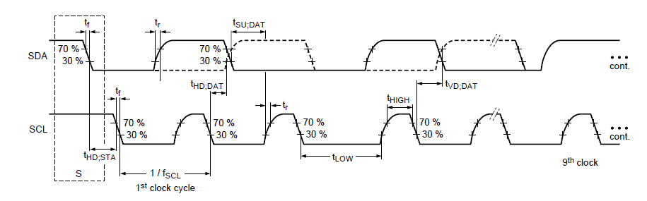
The mainly part of parameter configuration I2C is the configuration of I2C frequency. The I2C frequency can be matched not only related to the chip but also I2C SCL and SDA rise time, because the I2C standard protocol has requirements for rising and falling edge time, especially rising time. If the maximum value specified by the protocol is exceeded, the I2C communication may fail. The following is the maximum and minimum value specified in the protocol and figure shows the relationship between them:

The rising edge Tr and the falling edge Tf need to be measured with an oscilloscope, refer to the following diagram:
The I2C driver i2c-rk3x.c and i2c-rockchip.c are not the same. The differences are as follows:
Configuration for drive i2c-rk3x.c
The configuration of the i2c-rk3x.c driver is in DTS, reference file is Documentation/devicetree/bindings/i2c/i2c-rk3x.txt. Here highlight the configuration items, i2c-scl-rising-time-ns, i2c-scl-falling-time-ns:
- clock-frequency: The default frequency is 100k, the default frequency can be remained, the other I2C frequencies need to do configuration. The maximum configurable frequency is determined by i2c-scl-rising-time-ns. For example to configure 400k, set
clock-frequency=<400000>;at dts. - i2c-scl-rising-time-ns: The rise time of SCL is determined by hardware and changing the pull-up resistor can adjust the time. It needs to be measured by oscilloscope, refer to the above figure; for example, measure the rise edge of SCL is 265ns, set
i2c-scl-rising-time-ns=<265>;at dts. (The default rising time can be remained, but the current rising edge time must be ensured that it is under the maximum rising edge time which defined by the I2C standard for the configured frequency). - i2c-scl-falling-time-ns: The SCL fall edge time, which has no change generally , is equivalent to i2c-sda-falling-time-ns. (The default is also no need to configure).
&i2c1 {
	status = "okay";
	i2c-scl-rising-time-ns = <265>;
	i2c-scl-falling-time-ns = <11>;
	clock-frequency = <400000>;

	es8316: es8316@10 {
		#sound-dai-cells = <0>;
		compatible = "everest,es8316";
		reg = <0x10>;
		clocks = <&cru SCLK_I2S_8CH_OUT>;
		clock-names = "mclk";
		spk-con-gpio = <&gpio0 11 GPIO_ACTIVE_HIGH>;
		hp-det-gpio = <&gpio4 28 GPIO_ACTIVE_LOW>;
	};
};
Configuration for driver i2c-rockchip.c
The i2c-rockchip.c driver still follows the constraint relationship between the I2C frequency and the rise edge of SCL. Whether the higher frequency can be used depends on i2c-scl-rising-time-ns; the I2C frequency is configured on the code scl_rate member at the i2c_msg structure directly. The default frequency is still 100k, such as the following 200K configuration:
        struct i2c_msg xfer_msg;

        xfer_msg[0].addr = client->addr;
        xfer_msg[0].len = num;
        xfer_msg[0].flags = client->flags;
        xfer_msg[0].buf = buf;
        xfer_msg[0].scl_rate = 200 * 1000; /* 200K i2c clock frequency */
I2C usage
The further instructions for using I2C are in Documentation/i2c/*. The following sections focus on the read and write sections:
Kernel space
Rockchip I2C sending and receiving communication uses the standard interface of Linux. Please refer to the Documentation/i2c/writing-clients under kernel for a description of the sending and receiving section.
User space
Typically, I2C devices are controlled by the kernel driver. However, all devices on the bus can also be accessed from the user mode through the /dev/i2c-%d interface. Documentation/i2c/dev-interface under the kernel has further descriptions and examples.
I2C tools
I2C tool is an open source tool, you can download it and cross-compile. The code download address is: https://www.kernel.org/pub/software/utils/i2c-tools/ OR git clone git://git.kernel.org/pub/scm/utils/i2c-tools/i2c-tools.git
After compiling, it will generate tools such as i2cdetect, i2cdump, i2cset, i2cget, i2ctransfer, which can be used directly on the command line. The I2C tool are all open source. Please refer to the README and help instructions for compilation and using.
GPIO simulation as I2C
I2C is simulated with GPIO and the kernel has been implemented. Please refer to the documentation:
Documentation/devicetree/bindings/i2c/i2c-gpio.txt
The following is an example of using I2C nodes at dts.
        i2c@4 {
                compatible = "i2c-gpio";
                gpios = <&gpio5 9 GPIO_ACTIVE_HIGH>, /* sda */
                        <&gpio5 8 GPIO_ACTIVE_HIGH>; /* scl */
                i2c-gpio,delay-us = <2>;        /* ~100 kHz */
                #address-cells = <1>;
                #size-cells = <0>;
                pinctrl-names = "default";
                pinctrl-0 = <&i2c4_gpio>;
                status = "okay";

                gt9xx: gt9xx@14 {
                        compatible = "goodix,gt9xx";
                        reg = <0x14>;
                        touch-gpio = <&gpio5 11 IRQ_TYPE_LEVEL_LOW>;
                        reset-gpio = <&gpio5 10 GPIO_ACTIVE_HIGH>;
                        max-x = <1200>;
                        max-y = <1900>;
                        tp-size = <911>;
                        tp-supply = <&vcc_tp>;
                        status = "okay";
                };
        };
GPIO method is generally not recommended due to low efficient.
I2C FAQ
Because we have two i2c drivers, so this chapter still have two parts:
i2c-rk3x.c Driver
NACK Error
If the return value of the I2C transport interface is -6 (-ENXIO), it is indicated as a NACK error, that is, the slave device does not respond, this problem usually is located at peripheral. The following are common cases:
- I2C address is incorrect;
- The I2C slave device is in an error working state, such as no power-on, incorrect power-on sequence, and device error.
- The I2C timing does not meet the requirements of the slave device , which also generates a NACK signal. For example, the slave device needs the stop signal while receives the repeat start signal, NACK signal will occur.
- The I2C bus bug caused by external signal can be seen when measured with an oscilloscope.
Timeout Error
Case 1
When I2C log is timeout, ipd: 0x00, state: 1 occurs, the I2C controller is working irregularly and it cannot generate an interrupt status, the start timing cannot be sent. There are several possibilities:
- I2C SCL or SDA Pin IO-MUX error;
- The pull-up voltage of I2C is incorrect, such as insufficient voltage or with no pull-up power supply;
- The I2C pin is held by the peripheral hardware and the voltage is incorrect;
- The I2C clock is not enabled, or the clock source is too small;
- I2C is configured with both the CON_START and CON_STOP bits.
Case 2
When the I2C log is timeout, ipd: 0x10, state: 1 occurs, the I2C controller is working properly, but the CPU cannot respond to the I2C interrupt. At this time, cpu0 may be blocked (generally the I2C interrupt is on cpu0, It can be viewed by command cat /proc/interrups), or the I2C interrupt source may be turned off make the irq can not trigger cpu to handle it.
Case 3
When the I2C log is timeout, ipd: 0x80, state: 1 occurs, the ipd is 0x80, which means that the current SCL is held by the slave, you need to find it was held by which slave for more slave case:
- The first method is exclusion, which is applicable to the case where there are not many peripherals, and the probability of recurrence is high;
- Second method, the hardware needs to be modified. The resistor is serially connected to the SCL bus. The voltage difference generated across the resistor is used to determine that the lower-side peripheral is the slave that is pulled low. The selection of the resistor can not affect the I2C transmission, which also should generate voltage difference. Generally, it can be 1/20 of the pull-up resistor or more. And the voltage difference can also be seen if the host pulled down the voltage. In addition, based on this, it is more intuitive to capture the waveform through the oscilloscope. Compare the low level voltage of different slaves and host, find the low level voltage which matches the value while problem occurring. The corresponding slave devices or host which equals the low level voltage value is the reason to pull down the voltage of the bus.
The common situation is that SDA is pulled down. To prove who is pulling down, also refer to the above method of "SCL is pulled down".
i2c-rockchip.c Driver
NACK Error
If the return value of the I2C transport interface is -11(-EAGAIN), it is indicated as a NACK error, that is, the other device does not respond. This problem usually is located at slave devices. The following are common cases:
- I2C address is incorrect;
- The I2C slave device is in an error working state, such as no power-on, incorrect power-on sequence, and device error.
- The I2C timing does not meet the requirements of the slave device, which also generates a NACK signal. For example, the slave device needs the stop signal while receives the repeat start signal, NACK signal will occur.
- The I2C bus bug caused by external signal can be seen when measured with an oscilloscope.
Timeout Error
Case 1
When I2C log is timeout, ipd: 0x00, state: 1 occurs, the I2C controller is working irregularly and it cannot generate an interrupt status, the start timing cannot be sent. There are several possibilities:
- I2C SCL or SDA Pin IO-MUX error;
- The pull-up voltage of I2C is incorrect, such as insufficient voltage or with no pull-up power supply;
- The I2C pin is held by the peripheral hardware and the voltage is incorrect.
- The I2C clock is not enabled, or the clock source is too small;
- I2C is configured with both the CON_START and CON_STOP bits.
Case 2
When the I2C log is timeout, ipd: 0x10, state: 1 occurs, the I2C controller is working properly, but the CPU cannot respond to the I2C interrupt. At this time, cpu0 may be blocked (generally the I2C interrupt is on cpu0, It can be viewed by command cat /proc/interrups), or the I2C interrupt source may be turned off make the irq can not trigger cpu to handle it.
Case 3
When the I2C log timeout, ipd: 0x80, state: 1 occurs, here ipd is 0x80, or the printed scl was hold by slave, which means that the current SCL is held by the slave, you need to find it was held by which slave for more slave case:
- The firtst method is exclusion, which is applicable to the case where there are not many peripherals, and the probability of recurrence is high;
- Second method, the hardware needs to be modified. The resistor is serially connected to the SCL bus. The voltage difference generated across the resistor is used to determine that the lower-side peripheral is the slave that is pulled low. The selection of the resistor can not affect the I2C transmission, which also should generate voltage difference. Generally, it can be 1/20 of the pull-up resistor or more. And the voltage difference can also be seen if the host pulled down the voltage. In addition, based on this, it is more intuitive to capture the waveform through the oscilloscope. Compare the low level voltage of different slaves and host, find the low level voltage which matches the value while problem occurring. The corresponding slave devices or host which equals the low level voltage value is the reason to pull down the voltage of the bus.
The common situation is that SDA is pulled down. To prove who is pulling down, also refer to the above method of SCL is pulled down.
When the log is i2c is not in idle (state =x) occurs, it indicates that at least one I2C bus is low. For the solution, refer to the above:
- "state=1" means SDA is low;
- "state=2" means SCL is low;
- "state=3" means SCL and SDA are both low.
I2C waveform
If the I2C problem you meet is not mentioned here, the best way is to grab the waveform when the I2C error occurs and analyze the I2C problem through the waveform. The waveform of I2C is very useful, which can figure out most of the problems; You can operate to stuck the current i2c task(sch as while(1), etc.) while error occurring, the finally captured in oscilloscope is the waveform for the error. If you need to filter, you can also add the condition such as the device I2C address, etc.