Interface Details
Front interfaces
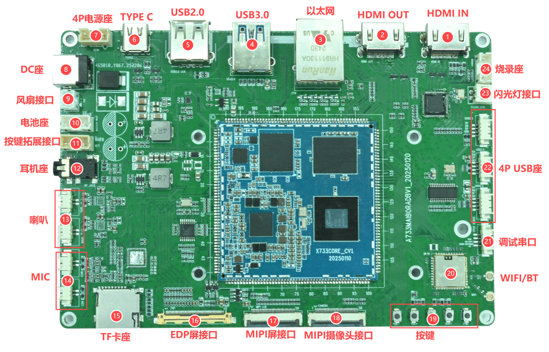
| No. | Interface | Purpose |
|---|---|---|
| 1 | HDMI IN | HDMI input through LT6911C |
| 2 | HDMI OUT | Native A733 HDMI output |
| 3 | Gigabit Ethernet | RTL8211F over RGMII |
| 4 | USB 3.0 | USB 3.0 Host |
| 5 | USB 2.0 Type-A | USB 2.0 Host |
| 6 | Type-C | OTG, firmware download and ADB |
| 7 | 4-pin power | Auxiliary 12 V input |
| 8 | DC jack | 12 V input |
| 9 | Fan | 12 V fan |
| 10 | Battery | Battery input and temperature sense |
| 11 | External keys | BOOT, RST and PWRON |
| 12 | Headphone | Headphone/headset output |
| 13 | Speakers | Stereo speaker outputs |
| 14 | Microphones | Two analog microphone inputs |
| 15 | TF card | Boot or data storage |
| 16 | eDP display | 40-pin eDP connector |
| 17 | MIPI display | 30-pin MIPI DSI connector |
| 18 | MIPI camera | 30-pin 4-lane MIPI CSI connector |
| 19 | Keys | VOL-, VOL+, RST, BOOT and PWRON |
| 20 | Wi-Fi/BT | AW869A module |
| 21 | Debug UART | UART0, 4-pin 1.25 mm connector |
| 22 | 4-pin USB | Three USB 2.0 headers |
| 23 | Flash LED | 3.3 V flash-light connector |
| 24 | LT6911C programming | LT6911C configuration/programming |
Rear interface
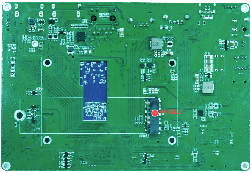
The rear M.2 socket is intended for storage expansion. Supported keying, protocol, device length and power capability must be confirmed against the schematic and BOM.
Power and battery
The board uses 12 V DC input; a 12 V / 3 A adapter is recommended. The DC jack and the 4-pin connector are 12 V input paths and polarity must be verified before connection.
The battery connector exposes VBAT, TS and GND. TS is the battery temperature-sense signal and must not be treated as a power pin.
USB
- Type-C is the OTG/device port for PhoenixSuit and ADB.
- One Type-A connector provides USB 3.0 Host.
- FE1.1S expands USB 2.0 into one Type-A port and three 4-pin headers.
- The headers can be used for USB touch panels and other USB 2.0 devices.
HDMI input/output
HDMI OUT is native to A733. HDMI IN is converted to MIPI CSI by LT6911C and is exposed to software as a capture/camera pipeline:
HDMI Source -> LT6911C -> MIPI CSI -> CSI/ISP/VIPP -> Android Application
Debugging must include LT6911C firmware, I2C, reset, interrupt, MIPI lanes, video format and the media graph.
Display and camera
- The MIPI DSI connector includes four data lanes, clock, panel rails, touch I2C/interrupt/reset, backlight PWM and panel reset.
- The eDP connector includes four main lanes, AUX, HPD, 3.3 V panel power, 12 V backlight power, enable/PWM and touch I2C.
- The MIPI CSI connector includes four data lanes, clock, I2C, MCLK, reset/standby and camera supply rails.
See Connector Pinout for complete tables.
Audio, keys and cooling
- Two differential
MICP/MICNmicrophone connectors are provided. - Stereo speaker outputs are rated at 3 W@8 Ω.
- Onboard keys are
VOL-,VOL+,RST,BOOTandPWRON. - The fan connector outputs 12 V and must not be used with a 5 V fan.