Interface Details
Power Input
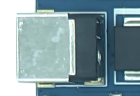
The board uses a 12V DC input. The standard package in the hardware manual includes a 12V/2A adapter.
Gigabit Ethernet
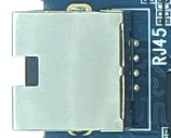
An RTL8211F Gigabit Ethernet PHY is fitted. Network configuration is handled by Android or Linux.
TF Card
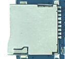
One TF card slot is provided for storage expansion and file transfer.
Parallel Camera
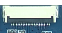
The 24-pin connector carries the parallel camera bus. Confirm the module supply voltage and LDO setting.
MIPI CSI Camera
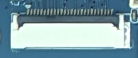
The 26-pin connector carries the MIPI CSI differential interface.
SIM and PCIe 4G Expansion
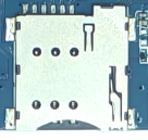
The SIM slot is used together with a PCIe 4G communication module.
FEL Upgrade Key
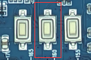
Hold FEL and reset or reapply power to enter the Allwinner USB upgrade mode.
Power Key
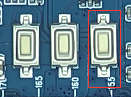
Used for power-on, Android suspend/resume, and software shutdown.
Reset Key
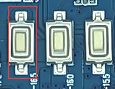
Performs a hardware reset while the system is running.
Key Header
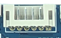
A 6-pin PH header exposes power, reset, and upgrade-key signals.
UART Headers
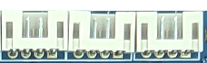
UART0 is the TTL debug port. UART2 and UART5 are selectable as TTL or RS-232.
I2C and SPI Headers
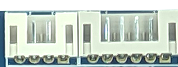
I2C and SPI expansion signals. Verify pin multiplexing and voltage domains from the schematic.
LCD and Backlight

The connectors are for backlight, LVDS, and multiplexed LVDS/RGB display signals.
HDMI
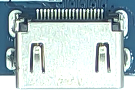
Type-A HDMI output for a monitor or television.
USB
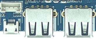
Two USB Host 2.0 Type-A ports and one Micro USB OTG port.
RTC Battery
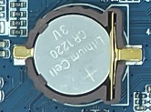
The backup battery maintains the RTC when main power is removed.
Wi-Fi/Bluetooth
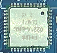
On-board 2.4GHz/5GHz dual-band Wi-Fi and Bluetooth module.