Interface Details
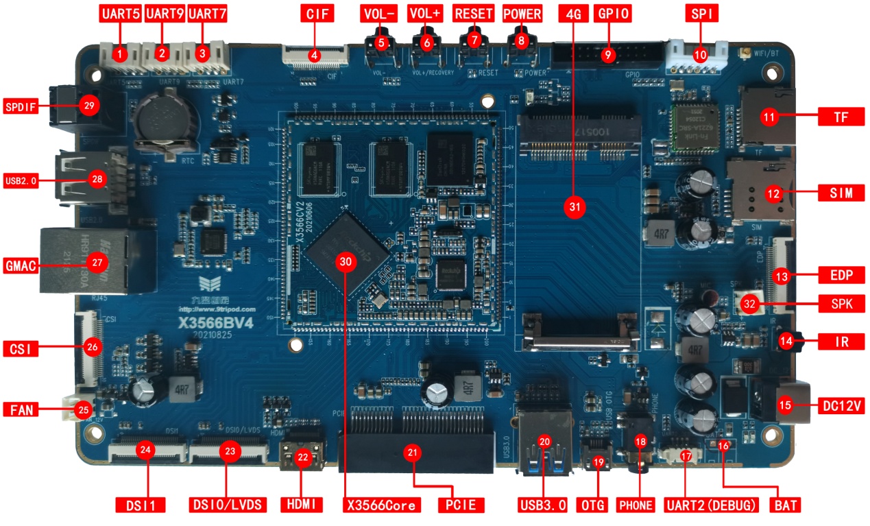
Power Input
X3566 uses a 12V DC power input. The DC jack is the 12V input connector.
Debug UART
UART2 is the default debug UART. The debug UART can be changed through software configuration.
HDMI
The board uses a mini HDMI connector. With a mini HDMI cable, audio and video can be output to HDMI2.0-capable displays.
Camera
CIF and CSI camera interfaces are reserved. OV-series cameras are supported. For different camera models, adjust voltage and driver configuration according to the camera specification.
Ethernet
One Gigabit Ethernet port is supported with the on-board YT8521SC PHY.
Headphone
The headphone jack provides headphone output and can also feed an external amplifier input.
Speaker
The board supports one 2W speaker output.
TF Card
The external TF card can be used for TF-card upgrade or multimedia storage.
Keys
There are four keys: two independent keys, PWRKEY, and RESET. Independent keys are sampled through ADC.
OTG
The OTG port is used for firmware download and related scenarios.
USB HOST2.0
RK3566 provides two HOST2.0 ports. One is exported through a standard Type-A connector, and the other is reserved for the 4G PCIe socket.
USB HOST3.0
One HOST3.0 channel is exported through a standard HOST3.0 connector.
Power Key
After external power is connected, hold PWRKEY to power on. In Android, press PWRKEY briefly for suspend/wake-up, and hold it to enter the power-off UI.
Reset
Press RESET during operation to reboot the board by hardware reset.
Recovery
The volume-up key is used as the Recovery key during flashing.
LCD
RK3566 supports dual DSI, LVDS, and EDP display interfaces. The left connector is DSI1; the right connector is DSI0/LVDS, selected by software.
Backup Battery
The backup battery keeps RTC running after main power is removed.
IR Receiver
The board uses an HS0038B integrated IR receiver for remote-control applications.
SPDIF Optical
Audio can be output through speaker, headphone, HDMI, and SPDIF optical.
Wi-Fi / Bluetooth
The board uses a 2.4G/5G dual-band SDIO Wi-Fi/BT module. Default model is 6221A-SRC, compatible with AP6398S, AP6375S, and other dual-band Wi-Fi modules.
UART
RK3566 includes 10 UARTs. The board reserves UART5, UART7, and UART9 as TTL UARTs through PH connectors, and UART2 as the debug UART.
PCIe
A standard PCIe connector is reserved for PCIe device expansion.
GPIO
A GPIO box header is reserved for GPIO expansion.