Interface Details
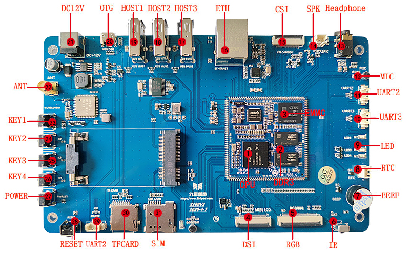
CPU / Memory / eMMC
The core platform is PX30: quad-core Cortex-A35 at 1.3GHz. X30CV1 defaults to 1GB DDR3 and 8GB eMMC, while X30CV2 uses LPDDR3.
DSI / LVDS / RGB Display
X30 reserves two display connectors: one for MIPI or LVDS, and one for RGB. MIPI and LVDS share the same pin group and cannot be used at the same time. PX30 has no native HDMI output; an external conversion chip is required for HDMI.
CSI Camera
PX30 supports MIPI and parallel cameras. The X30 board reserves only the MIPI camera connector, while the parallel camera pins are used for 100M Ethernet.
100M Ethernet
The board supports one 100M RMII Ethernet port. Some parallel-camera pins are multiplexed with Ethernet pins.
USB HOST / OTG
The board provides three USB USB HOST2.0 ports and one OTG port. OTG is used for firmware download and can also work as HOST when configured.
UART
UART3, UART2_M1, UART2_M0, and other TTL UARTs are available. UART2_M1 is the default debug UART. UART2_M0 shares pins with TF-card D0/D1 and must be selected in software.
TF Card
The TF card is used for external storage or upgrade. SDMMC0 D0/D1 are multiplexed with UART2.
Audio
PX30 with RK809 PMU provides audio codec functions for headphone, speaker, MIC, recording, and playback.
Keys / LED / Buzzer / IR
The board provides four independent keys, reset key, power key, four programmable LEDs, a buzzer, and an integrated IR receiver.
Wi-Fi / BT / 3G / 4G
AP6212 Wi-Fi/BT is on board. External mobile connectivity can be added through USB 3G or a PCIe module.
RTC
The board provides an RTC battery socket. The hardware manual emphasizes that RTC power must not be later than the main power input, otherwise PMU or CPU damage may occur.