Connector map
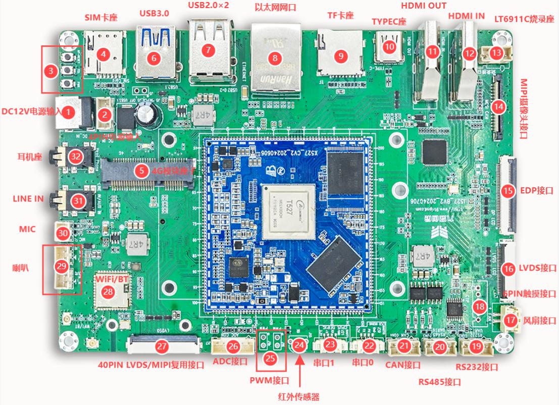
The front side provides 12 V power, RESET/FEL/POWER keys, SIM and PCIe 4G, USB 3.0, dual USB 2.0, Gigabit Ethernet, TF, Type-C OTG, HDMI OUT/IN, LT6911C programming, MIPI CSI, eDP, LVDS, fan, touch, RS232, RS485, two CAN channels, CPUX/CPUS debug UARTs, IR, PWM, ADC, LVDS/MIPI multiplexing, Wi-Fi/BT and audio connectors.
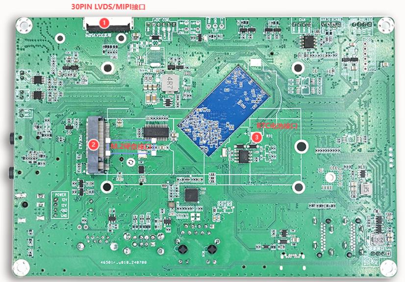
The rear side contains a 30-pin LVDS/MIPI connector, an M.2 expansion socket and an RTC backup-battery connector.
Power connector
| Pin | Signal |
|---|
| 1 | 12V |
| 2 | 12V |
| 3 | GND |
| 4 | GND |
Use a 12 V / 3 A supply. RESET resets the board, FEL enters the Allwinner flashing mode, and POWER controls power/suspend/wakeup behavior.
USB, network and expansion
- Type-C is the OTG/Device port used for PhoenixSuit flashing and ADB.
- One USB 3.0 Host and two USB 2.0 Host ports are available.
- RTL8211F provides Gigabit Ethernet over RGMII.
- The PCIe/SIM connector supports a 4G module.
- TF and M.2 provide storage expansion; verify the M.2 key/protocol against the schematic and BOM.
HDMI OUT is native to the SoC. HDMI IN is converted by LT6911C to a MIPI CSI stream.
| Pin | Signal |
|---|
| 1 | 3V3 |
| 2 | GND |
| 3 | SCL |
| 4 | SDA |
MIPI CSI camera connector
| Pin | Signal |
|---|
| 1 | GND |
| 2 | CAM-MDP2 |
| 3 | CAM-MDN2 |
| 4 | GND |
| 5 | CAM-MDP0 |
| 6 | CAM-MDN0 |
| 7 | GND |
| 8 | CAM-MCP |
| 9 | CAM-MCN |
| 10 | GND |
| 11 | CAM-MDP1 |
| 12 | CAM-MDN1 |
| 13 | GND |
| 14 | CAM-MDP3 |
| 15 | CAM-MDN3 |
| 16 | GND |
| 17 | MCSI_RESET |
| 18 | NC |
| 19 | SDA1 |
| 20 | SCK1 |
| 21 | MCLK |
| 22 | GND |
| 23 | VCCIO-CAM (1.8 V) |
| 24 | DVDD1V1 |
| 25 | AVDD2V9 |
| 26 | GND |
| 27 | SDA2 |
| 28 | SCK2 |
| 29 | NC |
| 30 | GND |
eDP connector
| Pin | Signal |
|---|
| 1 | NC |
| 2 | GND |
| 3 | DP-TX3N-1 |
| 4 | DP-TX3P-1 |
| 5 | GND |
| 6 | DP-TX2N-1 |
| 7 | DP-TX2P-1 |
| 8 | GND |
| 9 | DP-TX1N-1 |
| 10 | DP-TX1P-1 |
| 11 | GND |
| 12 | DP-TX0N-1 |
| 13 | DP-TX0P-1 |
| 14 | GND |
| 15 | DP-AUXP-1 |
| 16 | DP-AUXN-1 |
| 17 | GND |
| 18 | VCC-LCD-EDP (3.3 V) |
| 19 | VCC-LCD-EDP (3.3 V) |
| 20 | VCC-LCD-EDP (3.3 V) |
| 21 | VCC-LCD-EDP (3.3 V) |
| 22 | NC |
| 23 | GND |
| 24 | GND |
| 25 | GND |
| 26 | GND |
| 27 | DP-HPD-1 |
| 28 | GND |
| 29 | GND |
| 30 | GND |
| 31 | GND |
| 32 | LCD1-BL-PWREN |
| 33 | LCD1-BL-PWM |
| 34 | SDA |
| 35 | SCL |
| 36 | 12 V / 5 V |
| 37 | 12 V / 5 V |
| 38 | 12 V / 5 V |
| 39 | 12 V / 5 V |
| 40 | NC |
LVDS1 30-pin connector
| Pin | Signal |
|---|
| 1 | VCC_5V0 |
| 2 | VCC_5V0 |
| 3 | VCC_5V0 |
| 4 | VCC-LCD1 (3.3 V) |
| 5 | VCC-LCD1 (3.3 V) |
| 6 | CTP0-SCK |
| 7 | CTP0-SDA |
| 8 | CTP0-INT |
| 9 | CTP0-RST |
| 10 | VCC-LCD1 (3.3 V) |
| 11 | VCC-LCD1 (3.3 V) |
| 12 | LCD1-BL-PWM |
| 13 | LCD1_RST |
| 14 | NC |
| 15 | LCD1-BL-PWREN |
| 16 | GND |
| 17 | LVDS1_D3N |
| 18 | LVDS1_D3P |
| 19 | GND |
| 20 | LVDS1_D2N |
| 21 | LVDS1_D2P |
| 22 | GND |
| 23 | LVDS1_CKN |
| 24 | LVDS1_CKP |
| 25 | GND |
| 26 | LVDS1_D1N |
| 27 | LVDS1_D1P |
| 28 | GND |
| 29 | LVDS1_D0N |
| 30 | LVDS1_D0P |
40-pin LVDS0/MIPI DSI0 multiplexed connector
| Pin | Signal |
|---|
| 1 | NC |
| 2 | VCC-LCD (3.3 V) |
| 3 | VCC-LCD (3.3 V) |
| 4 | VCC-LCD (3.3 V) |
| 5 | NC |
| 6 | NC |
| 7 | NC |
| 8 | LVDS0-D0N / DSI0-D0N |
| 9 | LVDS0-D0P / DSI0-D0P |
| 10 | GND |
| 11 | LVDS0-D1N / DSI0-D1N |
| 12 | LVDS0-D1P / DSI0-D1P |
| 13 | GND |
| 14 | LVDS0-D2N / DSI0-CKN |
| 15 | LVDS0-D2P / DSI0-CKP |
| 16 | GND |
| 17 | LVDS0-CKN / DSI0-D2N |
| 18 | LVDS0-CKP / DSI0-D2P |
| 19 | GND |
| 20 | LVDS0-D3N / DSI0-D3N |
| 21 | LVDS0-D3P / DSI0-D3P |
| 22 | GND |
| 23 | NC |
| 24 | NC |
| 25 | GND |
| 26 | NC |
| 27 | NC |
| 28 | NC |
| 29 | NC |
| 30 | NC |
| 31 | GND |
| 32 | GND |
| 33 | GND |
| 34 | NC |
| 35 | LCD0-BL-PWM |
| 36 | VCC-LCD (3.3 V) |
| 37 | 3.3 V |
| 38 | VLED0+ (12 V) |
| 39 | VLED0+ (12 V) |
| 40 | VLED0+ (12 V) |
LVDS0 and DSI0 share the same high-speed pins and cannot be enabled simultaneously.
Rear 30-pin LVDS0/MIPI DSI0 connector
| Pin | Signal |
|---|
| 1 | VCC_5V0 |
| 2 | VCC_5V0 |
| 3 | VCC_5V0 |
| 4 | VCC-LCD1 (3.3 V) |
| 5 | VCC-LCD1 (3.3 V) |
| 6 | CTP0-SCK |
| 7 | CTP0-SDA |
| 8 | CTP0-INT |
| 9 | CTP0-RST |
| 10 | VCC-LCD1 (3.3 V) |
| 11 | VCC-LCD1 (3.3 V) |
| 12 | LCD1-BL-PWM |
| 13 | LCD1_RST |
| 14 | NC |
| 15 | LCD0-BL-PWREN |
| 16 | GND |
| 17 | LVDS0-D3N / DSI0-D3N |
| 18 | LVDS0-D3P / DSI0-D3P |
| 19 | GND |
| 20 | LVDS0-CKN / DSI0-D2N |
| 21 | LVDS0-CKP / DSI0-D2P |
| 22 | GND |
| 23 | LVDS0-D2N / DSI0-CKN |
| 24 | LVDS0-D2P / DSI0-CKP |
| 25 | GND |
| 26 | LVDS0-D1N / DSI0-D1N |
| 27 | LVDS0-D1P / DSI0-D1P |
| 28 | GND |
| 29 | LVDS0-D0N / DSI0-D0N |
| 30 | LVDS0-D0P / DSI0-D0P |
This connector shares the same LVDS0/DSI0 resource as the 40-pin connector.
Low-speed connectors
Touch
| Pin | Signal |
|---|
| 1 | 3V3 |
| 2 | GND |
| 3 | CTP0-INT |
| 4 | CTP0-RST |
| 5 | CTP0-SDA |
| 6 | CTP0-SCK |
RS232 / RS485 / CAN
| Interface | Pin assignment |
|---|
| RS232 | 3V3, TX, RX, GND |
| RS485 | 3V3, 485_A, 485_B, GND |
| CAN | CANH1, CANL1, CANH2, CANL2 |
Debug UARTs
- UART0 (CPUX):
GND, UART-0-CPUX-RX, UART-0-CPUX-TX, 3.3V
- UART1 (CPUS):
GND, CPUS-RX, CPUS-TX, 3.3V
| Pin | Signal |
|---|
| 1 | 1.8V |
| 2 | LRADC0 |
| 3 | LRADC1 |
| 4 | GPADC3 |
| 5 | GPADC4 |
| 6 | GND |
| 7 | PWRON |
| 8 | FEL |
| 9 | AP-RESET |
Audio, fan and RTC
The board provides two 0.5 W speaker outputs, a differential microphone input (MICIN1N/MICIN1P), line input and a headphone jack. The fan header is GND/12V. The RTC connector accepts a backup battery.