Interface Details
This page describes external connector usage and avoids repeating the full 200-pin table.
Power Input and Output
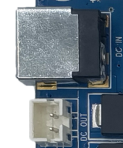
The board uses a 12V DC input. The white PH connector near the lower-left corner can be used as a 12V output for peripherals.
Debug UART
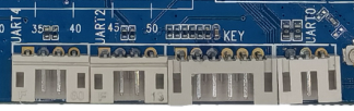
UART2 is the default debug serial port and is exported through a 4-pin PH connector. UART0 and UART4 are also exported through PH connectors.
HDMI
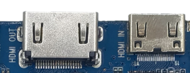
The board provides a standard Type-A HDMI connector for HDMI OUT and a mini Type-C style connector for HDMI IN.
Camera
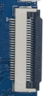
The FPC connector near the lower-right corner is a 26-pin camera interface. Camera power, reset, clock, and driver settings must match the selected module.
Ethernet
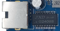
The board supports Gigabit Ethernet and uses the on-board YT8521 PHY.
Audio
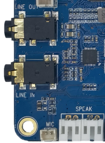
Audio interfaces include headset output, LINE IN, dual 2W speaker outputs, and MIC input.
TF Card
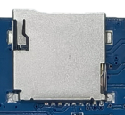
The external TF card slot can be used for firmware update, media storage, or external data storage.
Type-C

The Type-C interface supports USB OTG for flashing and data synchronization and can also be used for high-speed extension scenarios.
USB HOST
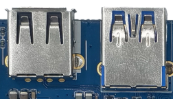
The board exposes USB3.0, USB HOST2.0, and several PH-header USB HOST2.0 interfaces for USB peripherals.
USB HOST2.0 Expansion
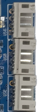
The right-side white PH connectors are USB HOST2.0 expansion connectors for internal USB modules or adapter cables.
Power / Reset / User Keys
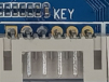
Reset and recovery-related keys are placed on the back side. Other power and user-key signals are exported through a 6-pin PH connector.
LCD / DSI / EDP
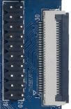
The board provides a 30-pin DSI connector, a 20-pin DSI header, and an EDP interface for high-resolution displays.
GPIO Expansion
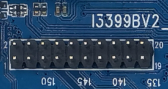
The GPIO header is used for external control, level detection, or low-speed peripheral expansion. Actual function depends on pinmux and device-tree configuration.
RTC Battery

The RTC battery connector keeps the real-time clock running when the main power is removed.
Buzzer
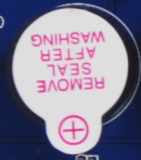
The active buzzer is controlled through a transistor and PWM signal. It can be used for PWM tests or audible notifications.
IR Receiver

The IR receiver uses an integrated HS0038B receiver and can be used for remote-control input.
SIM Card
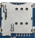
The SIM slot is used together with the PCIe 4G module. Insert the carrier SIM card when 4G network access is required.
PCIe
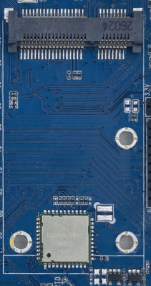
The PCIe connector can be used for a PCIe 4G module or other PCIe expansion device.
Wi-Fi / Bluetooth
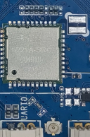
The board includes a 2.4G/5G dual-band SDIO Wi-Fi/Bluetooth module.