Hardware Resources
This page keeps the hardware overview only. For detailed connector usage, see Interface Details. For the 200-pin core-board definition, see Pin Definition.
Connector Location Map
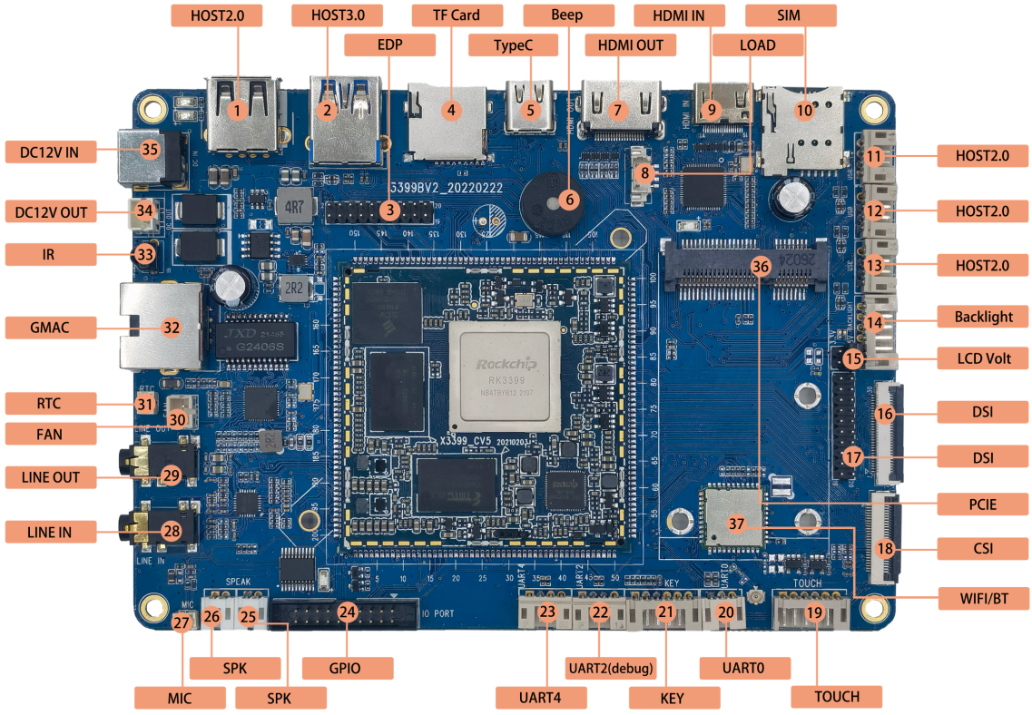
Hardware Interface Overview
| No. | Name | Description |
|---|---|---|
| 【1】 | USB HOST | HOST2.0 interface |
| 【2】 | USB HOST | HOST3.0 interface |
| 【3】 | EDP | EDP interface |
| 【4】 | TF Card | TF card holder |
| 【5】 | Type-C | TYPEC interface, compatible with OTG function |
| 【6】 | BEEP | buzzer |
| 【7】 | HDMI OUT | HDMI output interface |
| 【8】 | LOAD | HDMI IN chip program burning port |
| 【9】 | HDMI IN | HDMI input interface |
| 【10】 | SIM card slot | 3G, 4G mobile phone card slot |
| 【11】 | USB HOST | HOST2.0 interface |
| 【12】 | USB HOST | HOST2.0 interface |
| 【13】 | USB HOST | HOST2.0 interface |
| 【14】 | Backlight driver | LCD backlight driver interface |
| 【15】 | LCD voltage selection | 16, 17 mark the level selection of the display interface, 3.3V or 5V |
| 【16】 | MIPI DSI | Screen connected to MIPI interface, FPC interface |
| 【17】 | MIPI DSI | Screen connected to MIPI interface, pin header interface |
| 【18】 | MIPI CSI | MIPI camera interface |
| 【19】 | touch screen interface | I2C capacitive touch screen interface |
| 【20】 | serial port | uart0, TTL level |
| 【21】 | Button interface | 6PIN PH socket, button signal connection socket |
| 【22】 | UART2 | Serial port 2, TTL level, default debugging serial port |
| 【23】 | UART4 | UART4, TTL level interface |
| 【24】 | GPIO interface | Extended GPIO port |
| 【25】 | Speaker interface | External two-channel speakers |
| 【26】 | Speaker interface | External two-channel speakers |
| 【27】 | MIC | Headset interface |
| 【28】 | LINE IN | Audio input interface |
| 【29】 | LINE OUT | Headphone jack |
| 【30】 | Fan | Cooling fan power interface |
| 【31】 | RTC | RTC battery holder |
| 【32】 | GMAC / Ethernet | Gigabit Ethernet interface |
| 【33】 | Infrared receiver | HS0038 Infrared integrated receiver |
| 【34】 | DC OUT | 12V power output |
| 【35】 | DC IN | 12V DC power input |
| 【36】 | PCIE interface | Connect to the PCIE interface of 3G and 4G modules |
| 【37】 | WIFI、BT | 6221A-SRC, dual-band WIFI/BT module |
Software and Driver Support
I3399 supports Android 7.1, Qt, Ubuntu, and Debian-based systems. Common hardware functions include LCD/EDP, backlight, PMIC, touch, eMMC, SD card, keys, ADC, buzzer, IR, power management, USB HOST, USB OTG/Type-C, audio, camera, HDMI, PCIe/4G, GPS-related expansion, Ethernet, Wi-Fi/Bluetooth, and USB peripherals. The actual enabled functions depend on the firmware and hardware configuration delivered with the product.