Product Introduction
Product Overview
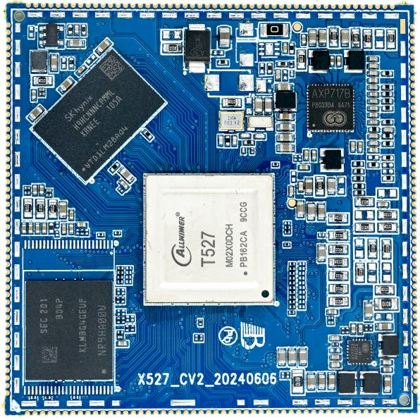
The X527CV2 is an eight-core Cortex-A55 core-board family based on the Allwinner T527/A527 series. Available pin-compatible variants include the T527N, T527, A527H, and A527M.
The 527 family supports DDR3, LPDDR3, DDR4, and LPDDR4(X), with CPU clocks up to 2GHz. Target applications include smart cockpits, surround-view systems, automated parking, edge computing, commercial displays, industrial control, and automotive electronics.
SoC Variants
| Model | CPU / NPU | Key Features | Temperature Grade |
|---|---|---|---|
| T527N | 8 × Cortex-A55 at 2.0GHz, 2TOPS NPU | Full-featured variant | Industrial, -40°C to 85°C |
| T527 | 8 × Cortex-A55 at 2.0GHz | No NPU | Industrial, -40°C to 85°C |
| A527H | 8 × Cortex-A55 at 2.0GHz | 4K + 1080p independent HDMI displays; no NPU; one fewer CAN and DSP channel | Commercial, -20°C to 75°C |
| A527M | 8 × Cortex-A55 at 1.8GHz | Commercial variant | Commercial, -20°C to 75°C |
| A523H | 8 × Cortex-A55 at 2.0GHz | Commercial variant | Commercial, -20°C to 75°C |
| A523M | 8 × Cortex-A55 at 1.8GHz | Commercial variant | Commercial, -20°C to 75°C |
Core Board Features
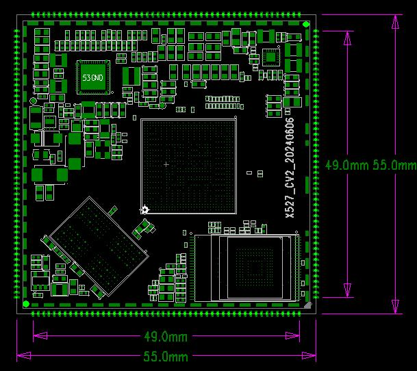
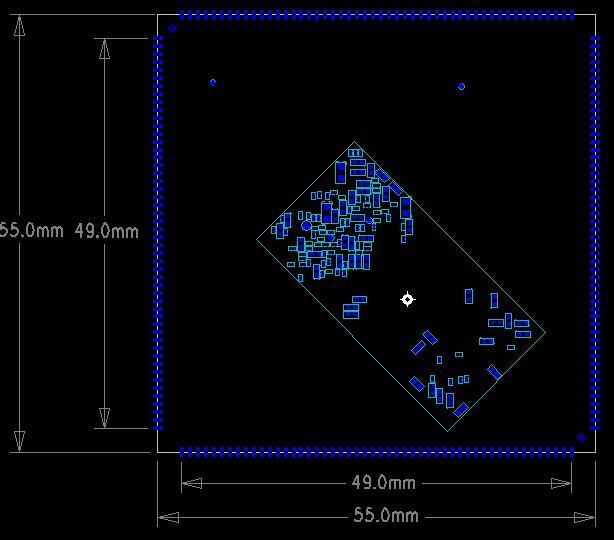
- 55mm × 55mm dimensions.
- PMU-based power management.
- Support for multiple eMMC brands and capacities.
- LPDDR4X memory with up to 4GB capacity.
- Sleep and wake-up support.
- Gigabit Ethernet, MIPI CSI, MIPI DSI, LVDS, RGB888, eDP, HDMI, PCIe, and USB3.0.
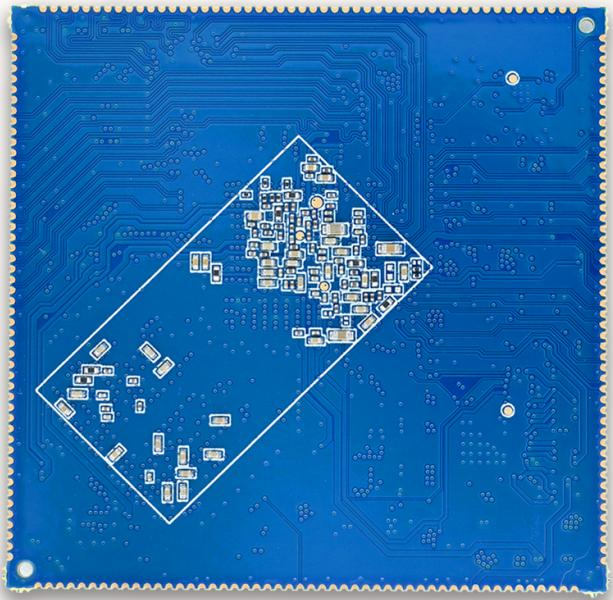
- 200-pin castellated/stamp-hole package.
- Pin-compatible T527N, T527, A527H, and A527M variants.
Appearance and Mechanical Drawings
Front View
Rear View
Top-Layer Mechanical Drawing
Bottom-Layer Mechanical Drawing
Specifications
System Configuration
| CPU | T527 / A527, Cortex-A55 |
|---|---|
| Clock | 2GHz |
| RAM | 2GB / 4GB LPDDR4X |
| ROM | 4GB / 8GB / 16GB / 32GB / 64GB / 128GB / 256GB eMMC |
| PMIC | AXP717B with dynamic frequency scaling support |
Interfaces
| LCD | Two LVDS, one eDP, and two MIPI interfaces selected by resistors |
|---|---|
| Audio | IIS / PCM / PDM / SPDIF |
| SD card | Two SDIO channels |
| eMMC | On-board eMMC; pins are not separately exposed |
| Ethernet | One Gigabit Ethernet interface |
| USB Host 2.0 | Three ports |
| USB Host 3.0 | One port |
| UART | 16 channels |
| I2C | The source parameter table does not state the channel count |
| Camera | The parameter table lists one MIPI CSI input |
| HDMI | One HDMI2.0 TX |
| PCIe | One PCIe2.0 interface |
Electrical Characteristics
| Input voltage/current | VCC-SYS, 5V / 3A |
|---|---|
| 3.3V outputs | DCDC4: 3.3V / 3A; CLDO3: 3.3V / 500mA |
| Operating temperature | -20°C to 85°C; -40°C to 85°C option |
| Storage temperature | -10°C to 50°C |
Mechanical Parameters
| Package | Castellated/stamp-hole module |
|---|---|
| Dimensions | 55mm × 55mm × 1.2mm |
| Pin pitch | 1.0mm |
| Pin count | 200 pins |
| PCB layers | 8 |
| Warpage | Less than 0.5% |